Affichage des articles dont le libellé est VOLTE. Afficher tous les articles

vendredi 15 mai 2020

thumbnail

TTI Bundling for better VOLTE HARQ and Latency

 TTI bundling enables a data block to be transmitted in consecutive TTIs, which are packed together and treated as the same resource during the scheduling process. TTI bundling makes use of  HARQ gains and reduces the number of re-transmissions and round trip time (RTT). When user’s  radio channel quality is degraded or the transmit power is limited (indication that UEs is closer to the cell edge), the TTI bundling can be triggered to improve the uplink coverage at cell-edge, reduce the number of different transmission segments at the  RLC layer and the re-transmission overhead.

For UEs at cell-edge  RLC packet is segmented first and mapped to MAC Transport Block (TB), then TTI bundling transmit same packets four times in one scheduling period to extend the coverage by increasing uplink transmission reliability. The eNodeB decides when to activate or deactivate the TTI bundling for certain users based on the measured signal-to-interference noise ratio (SINR) and PRB usage on uplink. The activation and deactivation is done by sending RRC reconfiguration message from eNodeB to UE.

RRC reconfiguration for TTI bundling

The data block in a bundle of TTIs, where the chunk of each bundle (up to 4 chunks), is modulated with different redundancy versions within the same HARQ identity. In the case of unsuccessful decoding of the HARQ identity, the eNodeB sends NACK the UE, which requires re-transmission. The resource allocation during this operation is restricted to a certain number of PRB and transport block size (TBS) in order to improve the probability of decoding at lower data rates.

The mechanism to transmit same packets four times in one scheduling instance expands the coverage by increasing the uplink transmission reliability with a better success rate gain. In addition, it guarantees that VoLTE packets are transmitted at cell-edge when resources are limited to improve the latency in bad radio conditions. TTI bundling is estimated to provide 2 – 4 dB uplink coverage improvement for VoLTE services which extend the cell radius for VoLTE service. 

Figure below describes the TTI bundling mechanism and provide comparison with a scheduling mechanism that depends only on RLC segmentation procedures.

RLC Segmentation without TTI Bundling


RLC Segmentation with TTI Bundling


TTI bundling advantages

The main advantage of TTI bundling is enhancing VoLTE uplink coverage when the UE has limited uplink transmit power. Thus, it guarantees better VoLTE QoS for cell-edge users.

In a conventional scheduling mechanism, if the UE is not able to accumulate sufficient power to transmit a small amount of data, like a VoIP packet, the data packets can be segmented into smaller size packets that fit within the UE transmit power. Each segment will be transmitted with a separate HARQ process. This segmentation mechanism increases the amount of control information that needs to be transmitted resulting in the control channel load increases with the amount of segments as every segment requires new transmission resources on these channels. Additionally, at cell-edge the probability for HARQ  NACK  increases with the number of segments causing higher uplink BLER . Therefore, the need to utilize better segmentation method like TTI Bundling is important.


Read also:


thumbnail

VoWiFi extends and enriches LTE VoLTE services

What is VoLTE and VoWiFi ?

Voice over Long-Term Evolution (VoLTE) is a standard high-speed wireless communication for mobile phones and data terminals. It is based on the IP Multimedia Subsystem (IMS) network, with specific profiles for control and media planes of voice service on the LTE wireless broadband service defined by GSMA. This approach results in the voice service (control and media planes) being delivered as data flows within the LTE data bearer, with no dependency on (or ultimately, requirement for) the circuit-switched voice network to be in the call path. VoLTE has up to three times more voice and data capacity than older 3G UMTS and up to six times more than 2G GSM. To be able to make a VoLTE call the device, its firmware, and the mobile telephony provider must all support the service in the area, and be able to work together.  


VoWi-Fi stands for Voice over (EPC-integrated) Wi-Fi. VoWi-Fi is a complementary technology to VoLTE and utilises IMS technology to provide a packet voice service delivered over IP via a Wi-Fi network. Where possible, VoLTE calls may be seamlessly handed over between LTE and Wi-Fi and vice versa.


What is the value of VoWiFi?

Both end-users and those in the mobile industry will benefit from Voice over Wi-Fi.

Consumers:

  • Can make calls without the need for a mobile signal (e.g. in a remote location or from within a property with thick walls
  • Benefit from security based on SIM-based authentication as for VoLTE
  • Experience better indoor coverage
  • Strong network security from a trusted operator that protects data from unlawful intercept and hacking.
  • Voice and video calling everywhere with service bundles that can lower rates and reduce roaming fees.

Operators:

  • Unlock revenue opportunities
  • Leverage existing SIM-based security and authentication as for VoLTE
  • Gain the opportunity to access IMS-based services via Wi-Fi access
  • Issue a single bill for the user for all IMS-based services across different access types
  • Gain a competitive advantage
  • Benefit from voice/video telephony services provided by IMS and the MMTEL application server as for VoLTE/ViLTE.

Challenges of adding Wi-Fi to LTE networks:

There are two main challenges:  

  1. Service continuity: Mobile device IP addresses must be preserved when moving between LTE and Wi-Fi, to ensure seamless handovers of calls and other network services such as enterprise VPNs.
  2. Service consistency/security: Public Wi-Fi networks are susceptible to hacking. Secure tunneling protocols and subscriber authentication methods are required.

EPC Architecture for LTE with WIFI access:

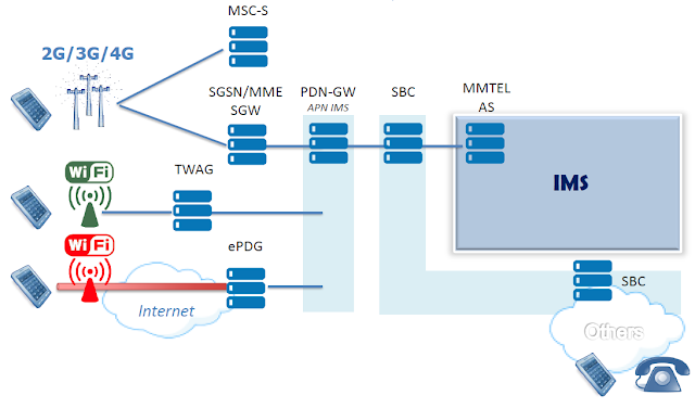
WIFI and LTE EPC Architecture

In the standards, Wi-Fi is considered a type of non-3GPP wireless access, which the MNO can view as either a trusted network or an untrusted network.To support these two network access types, two core network functions are needed:
  1. Evolved Packet Data Gateway (ePDG):  Supports the untrusted non-3GPP Wi-Fi access network
  2. Trusted Wireless Access Gateway (TWAG): Supports the trusted non-3GPP Wi-Fi access network

We will focus in this post on the ePDG, but both methods perform similar functions for their respective access networks:
  • Secure tunneling and aggregation of traffic from Wi-Fi access points (APs).
  • Interface to the AAA server for authentication of the mobile device to the EPC.
  • Access to the EPC via secure tunneling mechanisms (GTP or PMIP) to the MNO’s packet gateway (PGW) which provides the IP address for the mobile device.
  • Create the session request for bearer establishment and do the VoWiFi call data forwarding between the Wi-Fi access network and MNO’s PGW.
Although VoWiFi is the primary focus here, the method is transparent to the services (including Internet, enterprise VPNs and IMS).  Indeed, this is the beauty of the solution.  Implementation is relatively lightweight: an ePDG is added to the network and a slight update is made to the device’s client. In return, the solution works for any Wi-Fi AP (because no integration is required) and for any service (such as IMS, enterprise VPN and content delivery networks).  

The TWAG is similar, except it doesn’t require an update to the device, but does require integration with the Wi-Fi AP.

Read also:


TTI Bundling for better VOLTE HARQ and Latency

lundi 11 mai 2020

thumbnail

eSRVCC – Mind the coverage hole!


There are two big enemies of mobile communication. Weak signal and battery drain. With the LTE technology in place we need to deal with the situation when our signal gets too weak. The higher frequencies have a problem to penetrate walls, currently the radio network is not covering whole country yet, etc..  these problems seems to be only temporary (as the LTE is moving forward) but at this point of time we can’t rely on the LTE network only. When we are out of 4G coverage while we are not calling we’ll simply fallback to CS network and VoLTE supports CS breakout or CS retry so our voice service is still working.

But what if it happens during an ongoing call ? 
Can we handover and still maintain the session ?

It is possible but not easy as because of the battery drain we can access only one radio network at the time. What we are looking for is called Single Radio Voice Call Continuity (SRVCC). SRVCC is applied during PS to CS access transfer in a single radio system from LTE to 3G/2G.

SRVCC Scenarios and evolution

The main objective of SRVCC evolution is to imprve VOLTE user experience.
  • SRVCC – Access transfer without media anchoring – no ATCF/ATGW, SCC AS addressed by STN-SR (R9)
  • Emergency SRVCC – Support of access transfer for Emergency Calls (R9)
  • eSRVCC – Enhanced SRVCC – Media anchoring (+ mid-call feature support) (R10)
  • aSRVCC – Alerting SRVCC – Support of SRVCC PS-CS transfer of a call in alerting (ringing) phase (R10)
  • vSRVCC – Video Call support (R11)
  • rSRVCC – Reverse SRVCC – Support of access transfer from GSM/UTMS to LTE (R11)
  • bSRVCC – Before ringing SRVCC – Support of SRVCC PS-CS transfer of a call in pre-alerting phase (R12)

==> In this post we will focus on eSRVCC


eSRVCC is introduced to shorten the speech gap caused by SRVCC handovers. Media information on the UE does not need to be updated.
eSRVCC call flow is probably one of the most complex flows you can encounter in VoLTE. To allow this functionality we need to add some more IMS elements in the network:

  • Access Transfer Control Function (ATCF)

ATCF acts as SIP signalling anchor and is located in the SIP signalling path between P-SCSF and S-CSCF. Very often it is part of the SBC. ATCF controls the ATGW, where the media plane is anchored. During the session transfer, the ATCF establishes a new session with the SCC AS. This new session substitutes the old session between the ATCF and the SCC AS.

  • Access Transfer Gateway (ATGW)

The ATGW anchors the media session.

  • Service Centralization and Continuity Application Server (SCC AS)

The SCC AS anchors originated and terminated sessions when using the PS or CS access. It is also responsible for the Terminating Access Domain Selection (T-ADS).

IMS Architecture for eSRVCC


IMS Architecture for eSRVCC


As the new elements ATCF and SCC are anchoring the session we have also to modify the basic VoLTE flows.

Firstly we need to modify the registration. We have to send the information about what ATCF is responsible for the user to enhanced MSC/MGCF. This information is called Session Transfer Number for SRVCC (STN-SR) and it is a TEL URI of ATCF. 

Another important information which we need to exchange is the MSISDN which is being used by the user in the CS network. We call it Correlation MSISDN (C-MSISDN). 

And last but not least ATCF has to be able to address the SCC AS. The address is referenced as Transfer Update – Session Transfer Identifier (ATU-STI) and it is a SIP URI of SCC AS.

The flows for eSRVCC in IMS are described in 3GPP 23.237 and ETSI TS 124 237.

eSRVCC Registration

eSRVCC Registration


ATCF decides, based on the operator’s policy and if the home network supports eSRVCC with ATCF to alocate an STN-SR.  The ATCF decides to include itself for sessions created using this registration and adds its record in the Path: ATCF URI for terminating requests followed by P-CSCF URI for terminating requests. ATCF URI for terminating requests uniquely identifies registration (or registration flow, if multiple registration mechanism is used).

Then the ATCF forwards the SIP REGISTER request to the I-CSCF.

SCC AS will receive the STN-SR (the TPR contains the original SIP REGISTER in the body) and will update the ePC HSS. Then it’ll send its own uri – ATU-STI along with the C-MSISDN to ATCF as an xml payload of a SIP MESSAGE.

eSRVCC Call Flow


When a weak signal is detected the MME sends a handover request to CS network. Part of the request is the STN-SR and C-MSISDN. MSC/MGCF will create a new SIP INVITE and will send it to STN-SR e.g.

INVITE tel:+21622126927 SIP/2.0

ATCF finds the existing dialog for C-MSISDN (P-Asserted-Identity) and decides whether to anchor the media in the ATGW. Then sends a new SIP INVITE to SCC AS with the Target-Dialog which is to be transferred.

If the call is anchored in the SBC (ATGW) then we don’t need to renegotiate the SDP again. The SBC will simply do the translation between the access leg (e.g. narrow band) and remote leg (e.g. wide band). In case that this is not possible the SCC AS will send SIP UPDATE with the new SDP. This is something we are trying to avoid as it noticeably increases the delay during the transfer.