Affichage des articles dont le libellé est Antenna. Afficher tous les articles

mardi 19 mai 2020

thumbnail

What is ACTIVE ANTENNA UNIT and what are its benefits from 5G user experience perspective ?


An active antenna is an antenna that contains active electronic components like antenna-integrated radio designs place the RF module next to the passive antenna to reduce cable losses.
Active Antenna does not need to be merely passive elements. With intelligent integration, active antenna technology transforms traditional antenna to contribute to base station efficiency. This enables operators to significantly increase the capacity and coverage targets set for their network.
As a base station system evolved, the AAS integrated the active transceiver array and the passive antenna array into one radome.

In normal mode, RRH is connected to Antenna through RF cable. So there are two different units (one is RRH and second is antenna) , on the other hand, AAS is altogether single unit where different antenna elements has their own RF transceiver chains integrated.
AAS is integrated into the antenna so as to offer possibilities for finer grained digital control of the beamforming weight of each individual subelement within the antenna.


2D Vs 3D Antenna

AAS are introduced with 16 ports antenna (8 beams), before it we talk about passive 2D antenna. Its 3D-MIMO technologies fully utilize radio resources in both the micro- and macro-spatial domains.

3D Aspect of AAS
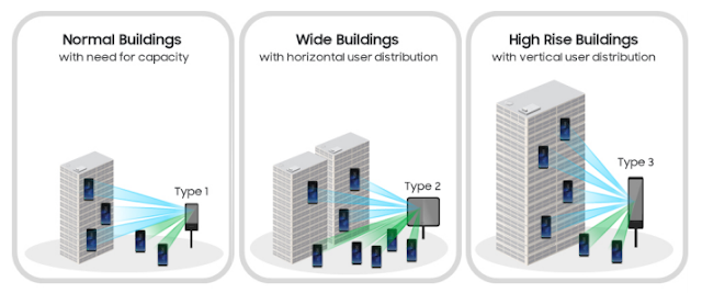

Traditionally and still, evaluations in the wireless communication field use channel models with only two dimensions, even though we live in a three-dimensional world. The vertical direction is basically non-existent in these models, all UEs are assumed to be placed on ground-level.

UE specific elevation beamforming is one key technique that we are exploring in the context of 3D channel models. It allows a beam to be directed in a way that suits each individual UE in the cell. For example, a UE high up in a high-rise may desire a beam pointing upwards, while a UE on the ground level may get a downwards pointing beam.

MU-MIMO


The term MIMO usually refers to Single User MIMO (SU-MIMO). In Single User MIMO, both the base station and UE have multiple antenna ports and antennas, and multiple data streams are transmitted simultaneously to the UE using same time/frequency resources, doubling (2×2 MIMO), or quadrupling (4×4 MIMO) the peak throughput of a single user.

In MU-MIMO, base station sends multiple data streams, one per UE, using the same time-frequency resources. Hence, MU-MIMO increases the total cell throughput, i.e. cell capacity. The base station has multiple antenna ports, as many as there are UEs receiving data simultaneously, and one antenna port is needed in each UE.

The performance potential of beamforming techniques tends to increase with an increasing number of antennas, since the baseband gets access to more degrees of spatial freedom. This is facilitated by techniques for active antenna systems (AAS) where the radio is integrated into the antenna so as to offer possibilities for finer grained digital control of the beamforming weight of each individual subelement within the antenna.

AAS for 5G


Massive MIMO is the back-bone for 5G network where 100 or more antenna elements are to be used for various benefits. But it is difficult to introduce massive-elements antennas (100 or more elements) that are required for massive MIMO into traditional base stations, attaching over 100 RF cables between each antenna element and RF TRX unit seems unrealistic and adding more RF losses. Using an AAS that combines the antennas, and RF TRX unit (transmitter and receiver chains), into one unit would be an effective way to resolve these issues.

In addition to the conventional roof top mounting locations, small cells are expected to cover shopping malls, Stadiums, food canteens, or different premises. To be effective, AAS/MIMO must be able to flexibly adapt to each individual small cell user’s distribution environment, so optimum antenna structure can be offered for any individual situation in terms of the number of vertical and horizontal antenna elements and the number of independent transceivers, adding huge efficiency to the network.

AAS BENEFITS

• Improved spectral efficiency and network capacity for higher throughput. The system sends and receives multiple data signals over the same radio channel, which increases the spectral efficiency per cell and the number of users who can be served simultaneously. This raises the peak and average cell throughput more cost-effectively than other techniques, such as new spectrum or additional sites.
• Stronger signal and reduction of interference for better coverage. Beamforming provides accurate and
narrow beams through aiming of the signal, which reduces interference and improves signal quality,
especially at the cell edge. Beamforming allows for expanded reach of the cell compared to traditional
antennas. This is particularly true for higher frequencies where beamforming compensates for the higher path loss.


vendredi 15 mai 2020

thumbnail

Atmospheric Duct Interference


Time-division duplex (TDD) is a technique allowing a telecommunication channel using the same transmission resource (a radio channel for example), to multiplex transmission and reception over time. This technique has a definite advantage in the case where the transmission and reception rates are variable and asymmetrical.  When the transmission rate increases or decreases, more or less bandwidth can be allocated.  Another advantage of this technique relates to mobile terminals moving at very low speed or in a fixed position. In this case, the beamforming technique is very effective with a TDD system.TD-LTE and 5G NR networks are adopting this technique to enhance capacity by using Mid band and High Band.

The interference source and localization of the mobile communication network, especially the Time Division Duplexing (TDD) system, becomes very complicated, especially when it becomes from natural phenomena.Atmospheric ducting is a mode of propagation of electromagnetic radiation, usually in the lower layers of Earth’s atmosphere, where the waves are bent by atmospheric refraction. For TDD system Atmospheric ducting can be a major source of intra-system interfrence.

This post mainly explain the basis of atmospheric duct interfrence for the Time Division Long Term Evolution (TD-LTE) system. It will proposes a centralized scheme to avoid such kind of interference through parameter optimization.

What is Atmospheric Duct Interference ?


With the low atmospheric duct effect, electromagnetic wave can bypass the ground plane and experiences trans-horizon propagation due to its small propagation loss like propagation in the atmospheric duct. If the remote eNodeB is located at a certain height, its large-power downlink signals can reach the local eNodeB after long-distance transmission. 

Because the long-distance transmission time exceeds the uplink/downlink guard interval, the downlink signals from the remote eNodeB are received by the local eNodeB in the receive timeslot of the local eNodeB, thereby interfering with uplink reception of the local eNodeB and producing remote co-channel interference. As a result, the network KPIs deteriorate mainly UL Interference and UL Throughput.

Methods and optimization for reducing the effects of atmospheric ducting interference:

Remote interference adaptive avoidance:

Due to atmospheric duct reciprocity, downlink signals of an eNodeB subject to remote interference caused by an atmospheric duct interfere with the uplink transmission of a remote eNodeB. When there is remote interference, the eNodeB periodically detects characteristic sequences in the UpPTS and uplink subframes. Based on the detection result, the eNodeB adjusts the special subframe configuration over the Uu interface and the guard period (GP) to reduce interference to the remote eNodeB. This method can be done manually by the optimizer or automatically when some features are already activate on the network.

Atmospheric duct downlink subframe shutdown:

Atmospheric duct interference is essentially the downlink interference caused by a remote eNodeB to the uplink reception of the local eNodeB. Therefore, interference to the local eNodeB can be eliminated as long as the downlink subframes of the remote eNodeB have no power output.  Based on the reciprocity of atmospheric duct, downlink service scheduling in subframes 0, 1, 5, and 6 can be disabled and scheduling of some CRS resources can be stopped on the local eNodeB when atmospheric duct interference occurs. This can reduce interference to the remote eNodeB and atmospheric duct interference on the entire network.

Optimized atmospheric duct downlink subframe shutdown:

Similar to atmospheric duct downlink subframe shutdown, this function is also based on atmospheric duct reciprocity. The eNodeB periodically detects interference in a cell and automatically performs cell-level subframe shutdown when atmospheric duct interference meets the threshold requirements. This method reduces atmospheric duct interference of the local cell to the entire network, improves the radio access and handover success rates, and decreases the service drop rate of the entire network. However, this function also provides negative gains to the local cell, decreasing the cell throughput and number of users and increasing the packet loss rate.


Read also:


TTI Bundling for better VOLTE HARQ and Latency

dimanche 28 septembre 2008

thumbnail

Beamforming


What Is Beamforming:

Beamforming is a downlink multi-antenna feature. With Beamforming, an eNodeB weights downlink data before transmission to form a narrow beam towards target UEs, thereby increasing the signal strength on the UE side. The direction of incoming wave and the path loss information are obtained by measuring the uplink received signal.  Beamforming is particularly important for the time division duplex (TDD) mode in LTE and 5G NR.

Weighting Process


Benefits:

An eNodeB direct beams towards target UEs in real time, increasing SINR especially for UEs at the cell edge.


Beamforming Technologies:


Single-Stream Beamforming:

  • Single-stream beamforming means transmission of a single data stream in the same OFDM resource block.
  • It is suitable for situations of poor channel quality.
  • Single-stream beamforming achieves diversity gain by 1 dB by increasing the SNR. 

Dual-Stream Beamforming:

  • Dual-stream beamforming means transmission of two data streams in the same OFDM resource block, leading to spatial multiplexing. 
  • It is suitable for situations of good channel quality. 

MU beamforming:

  • When MU beamforming is enabled, the eNodeB selects the UEs with high antenna channel correlations and low UE channel correlations for pairing due to the following reasons:
  1. If antenna channels are highly correlated and dual-stream beamforming is used, the data streams interfere with each other. In MU beamforming mode, the UEs with low channel correlations are paired. In this situation, spatial multiplexing gains are offered. 
  2. If antenna channels are lowly correlated, each UE can transmit multiple data streams and MU beamforming offers lower gains than dual-stream beamforming.

Beamformig TMs:

In LTE, usually they use multiple Antenna for downlink (at least from Category 3 UE and higher), meaning that eNode use multiple Tx Antenna and UE use multiple Rx antenna.
Now you almost automatically think about 'MIMO', but in reality 'multiple antenna' does not automatically mean 'MIMO'. For example, you have two downlink antenna. You can use these two antenna in various ways. Of course, one ways is to use it as 2 x 2 MIMO, but this is not the only way. You can use the two antenna in diversity configuration rather than MIMO configuration. Or you can just use only one of the antenna and sometimes you would like to use various different multiplexing, precoding methods etc.

The following table describes the available downlink transmission modes (TM) in LTE that are used with Beamforming as specified in 3GPP :
Transmission Mode 3GPP-Defined MIMO Technique Description
TM7 Single antenna port (port 5) In this mode, RSs are transmitted over antenna port 5 for single-stream beamforming.
TM8 Dual-layer transmission (ports 7 and 8) In this mode, RSs are transmitted over ports 7 and 8 for dual-stream beamforming
TM9 8 layer transmission Up to 8 layers, antenna ports 7 - 14