dimanche 29 novembre 2020

thumbnail

Dynamic spectrum sharing to accelerate nationwide 5G deployments


Wireless Service Providers can tap spectrum currently used for 4G to launch nationwide 5G coverage with a simple network software upgrade, and deploy a “5G Ready” network to operate on 4G today, with easy upgrade to 5G without disruption. Dynamic spectrum sharing is widely viewed as a key short-term enabler of scaling out 5G networks quickly. Rather than the slow, expensive process of re-farming spectrum from one generation connectivity technology to the next, DSS lets operators operate LTE and 5G NR in the same band at the same time.

What is Dynamic Spectrum Sharing (DSS) ?

Dynamic Spectrum Sharing (DSS) is emerging as a key part of mobile service providers’ 5G strategy. Using cellular base stations with DSS offers the lowest total cost of ownership (TCO) to launch 5G in bands currently used for 4G – enabling nationwide 5G coverage in short time after launch. Dynamic Spectrum Sharing allows an existing LTE carrier to operate 5G New Radio (NR) and LTE simultaneously – with a simple software upgrade. The solution is based on innovative intelligent scheduler algorithms that enable optimal performance as the mix of 4G and 5G devices in the network changes over time.

From the early stages of research into 5G NR, when developers began to map 5G transmissions to time-frequency resources, the developers created the possibility for holes in the 5G transmission grid which could be used for 4G LTE transmissions. This means that, by simultaneously sharing frequency bands which are already available today, service providers can fire up 5G on existing LTE bands without actually shutting off LTE. This means that, as well as having the option to roll out 5G on existing DSS-compatible 4G hardware, operators can keep the LTE network up and running while starting 5G. This can make it far easier for operators to transition to 5G in the coming years.

Dynamic spectrum sharing vs. static spectrum sharing


Static spectrum sharing or "spectrum re-farming" was a great transition from 2G and 3G to 4G. It's a very tiresome procedure with several constraints and huge preparation. Static spectrum sharing force mobile service providers to divise the spectrum betweend two rats with the same way all over the network and there is a high probability to impact network performances, otherwise it will create interference between RATs. Dynamic Spectrum Sharing will allow “soft” re-farming to NR with minimal impact to LTE performance.

Dynamic spectrum sharing advantages

Besides 5G NSA sites Wireless Service Providers can extend 5G coverage by activating DSS on 4G side network. DSS rollout benefits:
  • Resuse existing 4G spectrum
  • Resuse existing antenna
  • Reuse existing RF
  • Ressources shared dynamically between 4G and 5G

How does DSS work ?

The 5G physical layer is designed to be so similar to 4G in 3GPP that DSS becomes feasible with the same subcarrier spacing and similar time domain structure. DSS is designed to be backwards compatible with all existing LTE devices. Communication service providers (CSPs) therefore need to maintain LTE cell reference signal (CRS) transmission. 5G transmission is designed around LTE CRS in an approach called CRS rate matching.


Dynamic spectrum sharing scenarios


Wireless Service Providers can keep the existing 4G baseband and add a new 5G baseband. The scheduling between the two baseband functions is then based on a fast Xp interface between 4G and 5G. This interface is not open and works only for a single vendor, so CSPs must use the same vendor in 4G and 5G if they use DSS. Or deploy DSS with shared baseband card for 4G and for 5G, which obviously precludes a multi-vendor solution for 4G and 5G. The second solution it's the optimum scenario if the existing hardware supporting DSS Feature.

Frequency bands proposed for DSS between 4G and 5G 

Deploying 5G in low spectrum bands enhances network coverage. In general, low spectrum bands deliver wider coverage than high spectrum bands. As a result, mobile network operators need to secure additional low-band NR bands or deploy coverage densification solutions. 
By deploying 5G in low spectrum bands, coverage can be expanded at a faster rate. In addition, when 5G carrier aggregation (CA) is used to aggregate the low- and mid-bands, the control and signaling message can be transferred to the low frequency band, while the data rate can be boosted with extended coverage in mid-band. This has a direct improvement on the overall cell performance. As a result, mobile network operators can provide faster cell throughput and extended coverage.

Carrier aggregation between TDD bands and FDD Mid bands


samedi 23 mai 2020

thumbnail

Benefits of Self-Organizing Networks (SON) for Mobile Operators


Self-Organizing Networks (SON) is a collection of functions for automatic configuration, optimization, diagnostication and healing of cellular networks. It is considered to be necessity for latest mobile networks like 4G and 5G and operations due to the increased cost pressure and configuration complexity. The main drivers are essentially to reduce CAPEX and OPEX, which would otherwise increase dramatically due to increased number of network parameters that has to be monitored and set, the rapidly increasing numbers of base stations in the network and parallel operation of 2G, 3G, 4G and Evolved Packet Core (EPC) infrastructures. This post presents evaluations on the use of some of the most important SON components. Mobile networks are getting more complex to configure, optimize and maintain. Many SON functions will give cost savings and performance benefits from the very beginning of a network deployment and these should be prioritized now. But even if many functions are already available and can give large benefits, the field is still in its infancy and more advanced functions are either not yet implemented or have immature implementations. It is therefore necessary to have a strategy for how and when different SON functions should be introduced in mobile networks.

SON Architecture

There are three main alternatives regarding the architecture of SON functions in cellular networks as illustrated below. These are denoted centralized, distributed, and hybrid architectures. Different SON functions can be implemented by different architectures in the same network. In this chapter, we briefly describe the three different architecture options and discuss pros and cons of the different types.


Centralized SON Architecture

In a centralized SON architecture, the algorithms are executed at the network management level. Commands, requests and parameter settings data flow from the network management level to the network elements, while measurement data and reports flow in the opposite direction. The main benefit of this approach is that the SON algorithms can take information from all parts of the network into consideration , even an updated sites information like location (longitude and latitude) , design (azimut , tilt and Beamwidth ...), otherwise it will influense SON module' results. This means that it is possible to jointly optimize parameters of all centralized SON functions such that the network becomes more globally optimized, at least for slowly varying network characteristics. Also, centralized solutions can be more robust against network instabilities caused by the simultaneous operation of SON functions having conflicting goals. Since the control of all SON functions is done centrally, they can easily be coordinated.

Another advantage is that multivendor and third party SON solutions are possible, since functionality can be added at the network management level and not in the network elements where vendor specific solutions are usually required.

P.I.Works provides the industry-leading of  multi-vendor and multi-technology network optimization SON centralized solution.

The main drawbacks of the centralized SON architecture are longer response times, depends on CM and PM granularity and disponibility, increased backbone traffic, and that it represents a single point of failure. The longer response time limits how fast the network can adapt to changes and can even cause network instabilities. The backbone traffic increase since measurement data have to be sent from the network elements to the network management system and instructions must be sent in the opposite direction. This traffic will increase as more as cells are added to the network. If there are many pico- and femto-cells this traffic will be very significant. Also, the centralized processing power needed will be large.

Distributed SON Architecture

In a distributed SON architecture, the SON algorithms are run in the network nodes and the nodes exchange SON related messages directly with each other. This architecture can make the SON functions much more dynamic than centralized SON solutions, so that the network can adapt to changes much more quickly. It is also a solution that scales very well as the number of cells in the network increases.

4G eNodeB provides some distributed SON functions like Automatic Neighbor relations.  

The main drawbacks are that the sum of all the optimizations done at cell level do not necessarily result in optimum operation for the network as a whole and that it is more difficult to ensure that network instabilities do not occur.

Another drawback is that the implementation of the SON algorithm in the network elements will be vendor specific, so third party solutions will be difficult.

Even if the algorithms themselves are executed in the network elements, the network management system is usually able to control the behaviour of the SON function, for example, by setting the optimization criteria, receiving periodic reports, and being able to turn it off if necessary.

Hybrid SON Architecture

Hybrid SON solution means that part of the SON algorithm is run on the network management level and part is run in the network elements. The solution represents an attempt to combine the advantages of centralized and distributed SON solutions: centralized coordination of SON functions and the ability to respond quickly to changes at the network element level.

Unfortunately, the drawbacks of both centralized and distributed SON are also inherited. The SON related traffic in the backbone will be proportional to the number of network elements in the network, which means that it might not scale well. The same holds for the SON related processing required at the network management level. Also, since parts of the SON algorithms are running in the network elements and the interface between the centralized and distributed SON functions will be proprietary, third party solutions will be difficult.

It should be noted that the term “Hybrid SON” is not clearly defined and is used differently by different vendors. Some vendors classify their solutions as “hybrid” if the network management system can control the SON function by setting main parameters/policies, receiving reports and being able to turn it off if necessary. If such SON functions otherwise are autonomous, they are classified as “distributed”.

SON Functions

The SON functions are usually categorized into three main groups: self-configuration, self-optimization, and self-healing. It should be noted that a given SON function can belong to more than one of these categories.

Self-Configuration SON

The Self-configuration SON is a collection of algorithms that aims at reducing the amount of human intervention in the overall installation process by providing “plug and play” functionality in network elements such as the E-UTRAN NodeBs (eNBs). This will result in faster network deployment and reduced costs for the operator in addition to a more integral inventory management system that is less prone to human errors.

Self-configuration is a broad concept which involves several distinct functions that are covered through specific SON features, such as automatic software management, self test, physical cell ID configuration (PCI), and automatic neighbor relations (ANR). The latter function is not only used during installation but is also an important part during normal operations.

The self-configuration should take care of all soft-configuration aspects of an eNB once it is commissioned and powered up for the first time. It should detect the transport link and establish a connection with the core network elements, download and upgrade to the latest software version, set up the initial configuration parameters including neighbour relations, perform a self-test, and finally set itself to operational mode. In order to achieve these goals, the eNB should be able to communicate with several different entities.

The self-configuration actions will take place after the eNB is physically installed, plugged to the power line and to the transport link. When it is powered on, the eNB will boot and perform a self test, followed by a set of self-discovery functions, which include the detection of the transport type, tower-mounted amplifier (TMA), antenna, antenna cable length and auto-adjustment of the receiver-path.

After the self-detection function, the eNB will configure the physical transport link autonomously and establish a connection with the DHCP/DNS (dynamic host configuration protocol/domain name server) servers, which will then provide the IP addresses for the new node and those of the relevant network nodes, including serving gateway, mobility management entity (MME), and configuration server. After this, the eNB will be able to establish secure tunnels for operations sdministration and maintenance (OAM), S1, and X2 links and will be ready to communicate with the configuration server in order to acquire new configuration parameters.

One of the OAM tunnels created will communicate the eNB with a dedicated management entity, which contains the software package that is required to be installed. The eNB will then download and install the corresponding version of the eNB software, together with the eNB configuration file. Such configuration file contains the preconfigured radio parameters that were previously planned. A finer parameter optimization will take place after the eNB is in operational state (self-optimization functions).

The self-configuration SON functions were among the first standardized by 3GPP (release 8) and have been more or less stable since then. From the roadmaps of different vendors it can be concluded that self-configuration SON is available and mature. These SON features will be extremely useful in the rollout phase to reduce the installation time compared with ordinary installation procedures, and also later when new eNBs are added to increase the network capacity. The actual decrease in OPEX is not easy to give since the corresponding installation without any (self) automatic features is difficult to foresee.

Self-Optimization SON

SON self-optimization functions are aiming at maintaining network quality and performance with a minimum of manual intervention from the operator. Self-optimization functions monitors and analyzes performance data and automatically triggers optimization action on affected network element(s) when necessary. This significantly reduces manual interventions and replaces them with automatic adjustments keeping the network optimized at all times. Self-optimizing SON functions make it possible to introduce new automatic processes that are too fast, and/or too complex to be implemented manually. This will improve the network performance by making the network more dynamic and adaptable to varying traffic conditions and improve the user experience.

Some of the most important self-optimization SON use cases are:
  • 4G PCI/RSI and 3G PSC planning;
  • 3G/3G/4G Automatic neighbour relations (ANR);
  • 4G Inter-cell Interference coordination (ICIC);
  • 4G Mobility robustness optimization (MRO);
  • 3G/4G Mobility load balancing optimization (MLB);
  • 2G/3G/4G Cell Coverage optimization (CCO);
  • Energy Saving.
The two first use cases, PCI and ANR, may as well be categorized as self-configuration algorithms since they will be part of initial configuration procedures, but will also play an important part in normal operation and therefore may be viewed as being self-optimization procedures.

Self-Healing SON

Self-healing functionality was not initially defined a part of the 3GPP SON functionality, but it was taken into the SON standards in release 9 and 10, by 3GPP TS 32.541 “Self-healing concepts and requirements.

Self-healing is a collection of SON procedures which detects problems and solves or mitigates these to avoid user impact and to significantly reduce maintenance costs. Self-healing is triggered by alarms generated by the faulty network elements. If it finds alarms that it might be able to correct or minimize the effects of, it gathers more necessary correlated information (e.g., measurements, testing results, and so forth), does deep analysis, and then trigger the appropriate actions.

The two major areas where the self-healing concept could be applied are as follows.
  1. Self-diagnosis: create a model to diagnose, learning from past experiences.
  2. Self-healing: automatically start the corrective actions to solve the problem.

Making use and analyzing data from the current optimization tools (alarm supervision system, OAM system, network consistency checks), optimizers can decide if network degradation occurs, which is the most likely cause, and then perform the needed corrections to solve the problem. The experience of optimizers in solving such problems in the past, and the access to a database of historic solved problems is very useful to improve the efficiency in finding solutions.

This whole optimization process could be enhanced in two steps as follows.
  1. Diagnosis model creation based on the experience of already solved problems, using a database with faults and their symptoms. Automatic troubleshooting action can be done without human intervention.
  2. Self-test results from the periodic execution of consistency checks would help during the self diagnosis phase, to address better the healing process.
In the recommendation three different Self-healing SON functions are defined:
  1. Cell outage detection and compensation,
  2. Self-recovery of network element (NE) software,
  3. Self-healing of board faults.
For the time being only cell outage is available in vendor’s roadmaps and the two latter will therefore not be described in this post.

Coordination of SON Functions

Up to now, the work on SON has focused mostly on the development of stand-alone functionalities. However, several of the different SON functions may have the same target optimization parameters, that is, the output of two or more algorithms may try to act/optimize the same parameters. This may cause problems if some SON functions tend to tune parameters in different direction and this may lead to instabilities.

Such conflicts can occur if, for example, two different individual SON functions (e.g., cell outage management and interference coordination) aim at different goals when optimising the same parameter, or if the modification of a control parameter by one SON function influences the operation of other SON functions. Such conflicts may cause the whole system to operate far from optimal behaviour, with a negative impact on the operator’s overall objectives on performance and user satisfaction. Thus, the avoidance and/or resolution of conflicts and dependencies between the functions will be beneficial.

A good example of SON functions which need to be coordinated is MRO and MLB which both act and try to optimize the HO parameters and therefore needs to be coordinated.

As the SON suite grows it might be necessary to implement a framework for coordination of SON functions to ensure that the individual SON functions jointly work towards the same goal, formulated by the operator’s high-level objectives. This can be achieved by effectively and appropriately harmonising policies and control actions of the SON functions. A SON coordinator should furthermore ensure that the individual SON functions work with a common set of performance targets and measurements, and enable the operator to control the overall SON system through a single interface and thereby minimise the operational effort.

Initially it will be, at least, desirable to have coordination between some SON function like MRO/MLB and ANR/Phy cell ID. Later, as the SON suite grows in number, it will be necessary to introduce some form of SON coordination framework to secure optimal use of the SON suite.

SON Evolution

The inputs of SON has until now be limited to PM, CM and some design information for the development of functionalities. However, customers traces, Geo-location and CRM complaints may be a great inputs for some SON functions. This may enhance results if functions tend to tune parameters based on real user cahnnel quality, satisfaction and target quality of service.


mardi 19 mai 2020

thumbnail

What is ACTIVE ANTENNA UNIT and what are its benefits from 5G user experience perspective ?


An active antenna is an antenna that contains active electronic components like antenna-integrated radio designs place the RF module next to the passive antenna to reduce cable losses.
Active Antenna does not need to be merely passive elements. With intelligent integration, active antenna technology transforms traditional antenna to contribute to base station efficiency. This enables operators to significantly increase the capacity and coverage targets set for their network.
As a base station system evolved, the AAS integrated the active transceiver array and the passive antenna array into one radome.

In normal mode, RRH is connected to Antenna through RF cable. So there are two different units (one is RRH and second is antenna) , on the other hand, AAS is altogether single unit where different antenna elements has their own RF transceiver chains integrated.
AAS is integrated into the antenna so as to offer possibilities for finer grained digital control of the beamforming weight of each individual subelement within the antenna.


2D Vs 3D Antenna

AAS are introduced with 16 ports antenna (8 beams), before it we talk about passive 2D antenna. Its 3D-MIMO technologies fully utilize radio resources in both the micro- and macro-spatial domains.

3D Aspect of AAS


Traditionally and still, evaluations in the wireless communication field use channel models with only two dimensions, even though we live in a three-dimensional world. The vertical direction is basically non-existent in these models, all UEs are assumed to be placed on ground-level.

UE specific elevation beamforming is one key technique that we are exploring in the context of 3D channel models. It allows a beam to be directed in a way that suits each individual UE in the cell. For example, a UE high up in a high-rise may desire a beam pointing upwards, while a UE on the ground level may get a downwards pointing beam.

MU-MIMO


The term MIMO usually refers to Single User MIMO (SU-MIMO). In Single User MIMO, both the base station and UE have multiple antenna ports and antennas, and multiple data streams are transmitted simultaneously to the UE using same time/frequency resources, doubling (2×2 MIMO), or quadrupling (4×4 MIMO) the peak throughput of a single user.

In MU-MIMO, base station sends multiple data streams, one per UE, using the same time-frequency resources. Hence, MU-MIMO increases the total cell throughput, i.e. cell capacity. The base station has multiple antenna ports, as many as there are UEs receiving data simultaneously, and one antenna port is needed in each UE.

The performance potential of beamforming techniques tends to increase with an increasing number of antennas, since the baseband gets access to more degrees of spatial freedom. This is facilitated by techniques for active antenna systems (AAS) where the radio is integrated into the antenna so as to offer possibilities for finer grained digital control of the beamforming weight of each individual subelement within the antenna.

AAS for 5G


Massive MIMO is the back-bone for 5G network where 100 or more antenna elements are to be used for various benefits. But it is difficult to introduce massive-elements antennas (100 or more elements) that are required for massive MIMO into traditional base stations, attaching over 100 RF cables between each antenna element and RF TRX unit seems unrealistic and adding more RF losses. Using an AAS that combines the antennas, and RF TRX unit (transmitter and receiver chains), into one unit would be an effective way to resolve these issues.

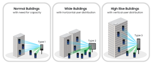
In addition to the conventional roof top mounting locations, small cells are expected to cover shopping malls, Stadiums, food canteens, or different premises. To be effective, AAS/MIMO must be able to flexibly adapt to each individual small cell user’s distribution environment, so optimum antenna structure can be offered for any individual situation in terms of the number of vertical and horizontal antenna elements and the number of independent transceivers, adding huge efficiency to the network.

AAS BENEFITS

• Improved spectral efficiency and network capacity for higher throughput. The system sends and receives multiple data signals over the same radio channel, which increases the spectral efficiency per cell and the number of users who can be served simultaneously. This raises the peak and average cell throughput more cost-effectively than other techniques, such as new spectrum or additional sites.
• Stronger signal and reduction of interference for better coverage. Beamforming provides accurate and
narrow beams through aiming of the signal, which reduces interference and improves signal quality,
especially at the cell edge. Beamforming allows for expanded reach of the cell compared to traditional
antennas. This is particularly true for higher frequencies where beamforming compensates for the higher path loss.


dimanche 17 mai 2020

thumbnail

New Radio For 5G


5G New Radio (NR) is the global standard for a unified, more capable 5G wireless air interface. It will deliver significantly faster and more responsive mobile broadband experiences, and extend mobile technology to connect and redefine a multitude of new industries.

5G has the business world abuzz with its possibilities. It’s expected to provide the connectivity that powers everything from autonomous cars to humanoid robots to smart homes. According to research, 70 percent of companies plan to have 5G use cases in production by 2021, with public transport, safety, agriculture and energy leading the way. So what are some of the most compelling use cases ?

The 3GPP specification for 5G states that the first roll-out of 5G networks and devices will be brought under Non-Standalone (NSA) operation, which is to say that the 5G networks will be supported by existing 4G infrastructure. Thus, 5G-enabled devices will connect to 5G frequencies for data user plane but will still use 4G for control plane such as signaling.


Single Framework, Multiple Usage Scenarios

The new radio (NR) specification targets a single technical framework addressing all usage scenarios, requirements and deployment scenarios including for enhanced mobile broadband (eMBB), massive machine-type-communications (mMTC) and ultra-reliable and low latency communications (URLLC).

Enhanced Mobile Broadband (eMMB)


The first roll-out of 5G wireless network will focus on enhanced mobile broadband (eMBB) to provide higher data-bandwidth and connection reliability via two NR frequency ranges:
  • Range 1 extends 4G LTE, from 450 MHz to 6,000 MHz. These bands are specified from 1 to 255 and this is mainly referred to as New Radio (NR) or sub-6GHz.

  • Range 2 is at a much higher frequency 24,250 MHz (~24GHz) to 52,600 MHz (~52GHz). These bands are specified from 257 to 511 and this is referred to as millimeter wave (mmWave).


Fixed Wireless Access (FWA)

Mobile service providers can use 5G to deepen their customer relationships, and extend into the home and workplace:
  • 5G enables home broadband, fast enough for gaming and high-definition video streaming.
  • 5G can also connect small and medium sized businesses, giving them guaranteed reliability for their business-critical applications.

Smart Stadiums

Service providers can sell new 5G services to venues, enabling them to:
  • Offer live 8K video from the pitch or the stage, with fans able to choose from multiple camera angles in real time.
  • Show data overlays and stats about musicians or players on the audience’s mobile or wearable devices.
  • Sell merchandise or additional services on the fly to customers using mobile devices.
  • Support pop-up retailers with secure wireless connections for payment processing.
  • Extend market reach, by offering the same live video and information feeds to fans who couldn’t get to the venue.


URLLC


        Ultra-reliable, low latency communications (URLLC) covers an entirely new use case family by supporting new requirements from vertical industries such as autonomous driving for the automotive industry, remote surgery for eHealth and cloud robotics for Industry 4.0. All applications demand:
  • Improved latency
  • Improved reliability
  • Higher availability
  • Higher security


The design of a low-latency and high-reliability service involves several components: Integrated frame structure, incredibly fast turnaround, efficient control and data resource sharing, grant-free based uplink transmission, and advanced channel coding schemes. In URLLC communications, < 1 ms latency is required to support demanding applications. That's why the designing of physical layer will be the most challenging thing as satisfying low latency and ultra-high reliability - two conflicting requirements at the same time is not an easy task. To fill this need , 5G NR introduces a flexible numerology to enable a wide range of frequencies and scheduling of diverse services that can be high throughput, low-latency, or even high latency for IoT applications. 
To ensure that , a scalable sub-carrier spacing is introduced by 5G , it enables scalable slot duration so that more slots can run in less time. To support future low-latency, mission-critical applications, a mini-slot is shorter in duration than a standard slot and can start at any time without waiting for the start of a slot boundary.

5G Possible Numerology


Massive Machine Type Communication (mMTC)


       Massive machine type communication (mMTC) also known as massive machine communication (MMC) or massive Machine to Machine communication is a type of communication between machines over wired or wireless networks where data generation, information exchange and actuation takes place with minimal or no intervention from humans. It is a sub-classification of machine type communication (MTC). mMTC deals particularly with wireless connectivity and networking amongst massive numbers (billions) of machines and is considered a key progression from the Internet of Things IoT to the Internet of Everything.


The development of mMTC is limited by the availability of the connectivity necessary to support vast numbers of machine to machine interactions. This type of communication is typically via small data packets which are not optimally supported by the cellular networks designed for human communication. Such networking would have to be secure, reliable and consistently scalable with high capacity and low latency to support a range of communications at varying frequency bands. mMTC also needs to have low cost and energy consumption with the penetration needed to function effectively in dense urban or indoor environments.


vendredi 15 mai 2020

thumbnail

TTI Bundling for better VOLTE HARQ and Latency

 TTI bundling enables a data block to be transmitted in consecutive TTIs, which are packed together and treated as the same resource during the scheduling process. TTI bundling makes use of  HARQ gains and reduces the number of re-transmissions and round trip time (RTT). When user’s  radio channel quality is degraded or the transmit power is limited (indication that UEs is closer to the cell edge), the TTI bundling can be triggered to improve the uplink coverage at cell-edge, reduce the number of different transmission segments at the  RLC layer and the re-transmission overhead.

For UEs at cell-edge  RLC packet is segmented first and mapped to MAC Transport Block (TB), then TTI bundling transmit same packets four times in one scheduling period to extend the coverage by increasing uplink transmission reliability. The eNodeB decides when to activate or deactivate the TTI bundling for certain users based on the measured signal-to-interference noise ratio (SINR) and PRB usage on uplink. The activation and deactivation is done by sending RRC reconfiguration message from eNodeB to UE.

RRC reconfiguration for TTI bundling

The data block in a bundle of TTIs, where the chunk of each bundle (up to 4 chunks), is modulated with different redundancy versions within the same HARQ identity. In the case of unsuccessful decoding of the HARQ identity, the eNodeB sends NACK the UE, which requires re-transmission. The resource allocation during this operation is restricted to a certain number of PRB and transport block size (TBS) in order to improve the probability of decoding at lower data rates.

The mechanism to transmit same packets four times in one scheduling instance expands the coverage by increasing the uplink transmission reliability with a better success rate gain. In addition, it guarantees that VoLTE packets are transmitted at cell-edge when resources are limited to improve the latency in bad radio conditions. TTI bundling is estimated to provide 2 – 4 dB uplink coverage improvement for VoLTE services which extend the cell radius for VoLTE service. 

Figure below describes the TTI bundling mechanism and provide comparison with a scheduling mechanism that depends only on RLC segmentation procedures.

RLC Segmentation without TTI Bundling


RLC Segmentation with TTI Bundling


TTI bundling advantages

The main advantage of TTI bundling is enhancing VoLTE uplink coverage when the UE has limited uplink transmit power. Thus, it guarantees better VoLTE QoS for cell-edge users.

In a conventional scheduling mechanism, if the UE is not able to accumulate sufficient power to transmit a small amount of data, like a VoIP packet, the data packets can be segmented into smaller size packets that fit within the UE transmit power. Each segment will be transmitted with a separate HARQ process. This segmentation mechanism increases the amount of control information that needs to be transmitted resulting in the control channel load increases with the amount of segments as every segment requires new transmission resources on these channels. Additionally, at cell-edge the probability for HARQ  NACK  increases with the number of segments causing higher uplink BLER . Therefore, the need to utilize better segmentation method like TTI Bundling is important.


Read also:


thumbnail

VoWiFi extends and enriches LTE VoLTE services

What is VoLTE and VoWiFi ?

Voice over Long-Term Evolution (VoLTE) is a standard high-speed wireless communication for mobile phones and data terminals. It is based on the IP Multimedia Subsystem (IMS) network, with specific profiles for control and media planes of voice service on the LTE wireless broadband service defined by GSMA. This approach results in the voice service (control and media planes) being delivered as data flows within the LTE data bearer, with no dependency on (or ultimately, requirement for) the circuit-switched voice network to be in the call path. VoLTE has up to three times more voice and data capacity than older 3G UMTS and up to six times more than 2G GSM. To be able to make a VoLTE call the device, its firmware, and the mobile telephony provider must all support the service in the area, and be able to work together.  


VoWi-Fi stands for Voice over (EPC-integrated) Wi-Fi. VoWi-Fi is a complementary technology to VoLTE and utilises IMS technology to provide a packet voice service delivered over IP via a Wi-Fi network. Where possible, VoLTE calls may be seamlessly handed over between LTE and Wi-Fi and vice versa.


What is the value of VoWiFi?

Both end-users and those in the mobile industry will benefit from Voice over Wi-Fi.

Consumers:

  • Can make calls without the need for a mobile signal (e.g. in a remote location or from within a property with thick walls
  • Benefit from security based on SIM-based authentication as for VoLTE
  • Experience better indoor coverage
  • Strong network security from a trusted operator that protects data from unlawful intercept and hacking.
  • Voice and video calling everywhere with service bundles that can lower rates and reduce roaming fees.

Operators:

  • Unlock revenue opportunities
  • Leverage existing SIM-based security and authentication as for VoLTE
  • Gain the opportunity to access IMS-based services via Wi-Fi access
  • Issue a single bill for the user for all IMS-based services across different access types
  • Gain a competitive advantage
  • Benefit from voice/video telephony services provided by IMS and the MMTEL application server as for VoLTE/ViLTE.

Challenges of adding Wi-Fi to LTE networks:

There are two main challenges:  

  1. Service continuity: Mobile device IP addresses must be preserved when moving between LTE and Wi-Fi, to ensure seamless handovers of calls and other network services such as enterprise VPNs.
  2. Service consistency/security: Public Wi-Fi networks are susceptible to hacking. Secure tunneling protocols and subscriber authentication methods are required.

EPC Architecture for LTE with WIFI access:

WIFI and LTE EPC Architecture

In the standards, Wi-Fi is considered a type of non-3GPP wireless access, which the MNO can view as either a trusted network or an untrusted network.To support these two network access types, two core network functions are needed:
  1. Evolved Packet Data Gateway (ePDG):  Supports the untrusted non-3GPP Wi-Fi access network
  2. Trusted Wireless Access Gateway (TWAG): Supports the trusted non-3GPP Wi-Fi access network

We will focus in this post on the ePDG, but both methods perform similar functions for their respective access networks:
  • Secure tunneling and aggregation of traffic from Wi-Fi access points (APs).
  • Interface to the AAA server for authentication of the mobile device to the EPC.
  • Access to the EPC via secure tunneling mechanisms (GTP or PMIP) to the MNO’s packet gateway (PGW) which provides the IP address for the mobile device.
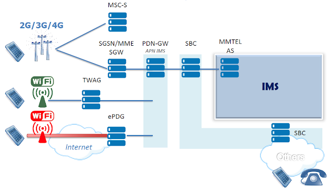
  • Create the session request for bearer establishment and do the VoWiFi call data forwarding between the Wi-Fi access network and MNO’s PGW.
Although VoWiFi is the primary focus here, the method is transparent to the services (including Internet, enterprise VPNs and IMS).  Indeed, this is the beauty of the solution.  Implementation is relatively lightweight: an ePDG is added to the network and a slight update is made to the device’s client. In return, the solution works for any Wi-Fi AP (because no integration is required) and for any service (such as IMS, enterprise VPN and content delivery networks).  

The TWAG is similar, except it doesn’t require an update to the device, but does require integration with the Wi-Fi AP.

Read also:


TTI Bundling for better VOLTE HARQ and Latency

thumbnail

Atmospheric Duct Interference


Time-division duplex (TDD) is a technique allowing a telecommunication channel using the same transmission resource (a radio channel for example), to multiplex transmission and reception over time. This technique has a definite advantage in the case where the transmission and reception rates are variable and asymmetrical.  When the transmission rate increases or decreases, more or less bandwidth can be allocated.  Another advantage of this technique relates to mobile terminals moving at very low speed or in a fixed position. In this case, the beamforming technique is very effective with a TDD system.TD-LTE and 5G NR networks are adopting this technique to enhance capacity by using Mid band and High Band.

The interference source and localization of the mobile communication network, especially the Time Division Duplexing (TDD) system, becomes very complicated, especially when it becomes from natural phenomena.Atmospheric ducting is a mode of propagation of electromagnetic radiation, usually in the lower layers of Earth’s atmosphere, where the waves are bent by atmospheric refraction. For TDD system Atmospheric ducting can be a major source of intra-system interfrence.

This post mainly explain the basis of atmospheric duct interfrence for the Time Division Long Term Evolution (TD-LTE) system. It will proposes a centralized scheme to avoid such kind of interference through parameter optimization.

What is Atmospheric Duct Interference ?


With the low atmospheric duct effect, electromagnetic wave can bypass the ground plane and experiences trans-horizon propagation due to its small propagation loss like propagation in the atmospheric duct. If the remote eNodeB is located at a certain height, its large-power downlink signals can reach the local eNodeB after long-distance transmission. 

Because the long-distance transmission time exceeds the uplink/downlink guard interval, the downlink signals from the remote eNodeB are received by the local eNodeB in the receive timeslot of the local eNodeB, thereby interfering with uplink reception of the local eNodeB and producing remote co-channel interference. As a result, the network KPIs deteriorate mainly UL Interference and UL Throughput.

Methods and optimization for reducing the effects of atmospheric ducting interference:

Remote interference adaptive avoidance:

Due to atmospheric duct reciprocity, downlink signals of an eNodeB subject to remote interference caused by an atmospheric duct interfere with the uplink transmission of a remote eNodeB. When there is remote interference, the eNodeB periodically detects characteristic sequences in the UpPTS and uplink subframes. Based on the detection result, the eNodeB adjusts the special subframe configuration over the Uu interface and the guard period (GP) to reduce interference to the remote eNodeB. This method can be done manually by the optimizer or automatically when some features are already activate on the network.

Atmospheric duct downlink subframe shutdown:

Atmospheric duct interference is essentially the downlink interference caused by a remote eNodeB to the uplink reception of the local eNodeB. Therefore, interference to the local eNodeB can be eliminated as long as the downlink subframes of the remote eNodeB have no power output.  Based on the reciprocity of atmospheric duct, downlink service scheduling in subframes 0, 1, 5, and 6 can be disabled and scheduling of some CRS resources can be stopped on the local eNodeB when atmospheric duct interference occurs. This can reduce interference to the remote eNodeB and atmospheric duct interference on the entire network.

Optimized atmospheric duct downlink subframe shutdown:

Similar to atmospheric duct downlink subframe shutdown, this function is also based on atmospheric duct reciprocity. The eNodeB periodically detects interference in a cell and automatically performs cell-level subframe shutdown when atmospheric duct interference meets the threshold requirements. This method reduces atmospheric duct interference of the local cell to the entire network, improves the radio access and handover success rates, and decreases the service drop rate of the entire network. However, this function also provides negative gains to the local cell, decreasing the cell throughput and number of users and increasing the packet loss rate.


Read also:


TTI Bundling for better VOLTE HARQ and Latency

lundi 11 mai 2020

thumbnail

eSRVCC – Mind the coverage hole!


There are two big enemies of mobile communication. Weak signal and battery drain. With the LTE technology in place we need to deal with the situation when our signal gets too weak. The higher frequencies have a problem to penetrate walls, currently the radio network is not covering whole country yet, etc..  these problems seems to be only temporary (as the LTE is moving forward) but at this point of time we can’t rely on the LTE network only. When we are out of 4G coverage while we are not calling we’ll simply fallback to CS network and VoLTE supports CS breakout or CS retry so our voice service is still working.

But what if it happens during an ongoing call ? 
Can we handover and still maintain the session ?

It is possible but not easy as because of the battery drain we can access only one radio network at the time. What we are looking for is called Single Radio Voice Call Continuity (SRVCC). SRVCC is applied during PS to CS access transfer in a single radio system from LTE to 3G/2G.

SRVCC Scenarios and evolution

The main objective of SRVCC evolution is to imprve VOLTE user experience.
  • SRVCC – Access transfer without media anchoring – no ATCF/ATGW, SCC AS addressed by STN-SR (R9)
  • Emergency SRVCC – Support of access transfer for Emergency Calls (R9)
  • eSRVCC – Enhanced SRVCC – Media anchoring (+ mid-call feature support) (R10)
  • aSRVCC – Alerting SRVCC – Support of SRVCC PS-CS transfer of a call in alerting (ringing) phase (R10)
  • vSRVCC – Video Call support (R11)
  • rSRVCC – Reverse SRVCC – Support of access transfer from GSM/UTMS to LTE (R11)
  • bSRVCC – Before ringing SRVCC – Support of SRVCC PS-CS transfer of a call in pre-alerting phase (R12)

==> In this post we will focus on eSRVCC


eSRVCC is introduced to shorten the speech gap caused by SRVCC handovers. Media information on the UE does not need to be updated.
eSRVCC call flow is probably one of the most complex flows you can encounter in VoLTE. To allow this functionality we need to add some more IMS elements in the network:

  • Access Transfer Control Function (ATCF)

ATCF acts as SIP signalling anchor and is located in the SIP signalling path between P-SCSF and S-CSCF. Very often it is part of the SBC. ATCF controls the ATGW, where the media plane is anchored. During the session transfer, the ATCF establishes a new session with the SCC AS. This new session substitutes the old session between the ATCF and the SCC AS.

  • Access Transfer Gateway (ATGW)

The ATGW anchors the media session.

  • Service Centralization and Continuity Application Server (SCC AS)

The SCC AS anchors originated and terminated sessions when using the PS or CS access. It is also responsible for the Terminating Access Domain Selection (T-ADS).

IMS Architecture for eSRVCC


IMS Architecture for eSRVCC


As the new elements ATCF and SCC are anchoring the session we have also to modify the basic VoLTE flows.

Firstly we need to modify the registration. We have to send the information about what ATCF is responsible for the user to enhanced MSC/MGCF. This information is called Session Transfer Number for SRVCC (STN-SR) and it is a TEL URI of ATCF. 

Another important information which we need to exchange is the MSISDN which is being used by the user in the CS network. We call it Correlation MSISDN (C-MSISDN)

And last but not least ATCF has to be able to address the SCC AS. The address is referenced as Transfer Update – Session Transfer Identifier (ATU-STI) and it is a SIP URI of SCC AS.

The flows for eSRVCC in IMS are described in 3GPP 23.237 and ETSI TS 124 237.

eSRVCC Registration

eSRVCC Registration


ATCF decides, based on the operator’s policy and if the home network supports eSRVCC with ATCF to alocate an STN-SR.  The ATCF decides to include itself for sessions created using this registration and adds its record in the Path: ATCF URI for terminating requests followed by P-CSCF URI for terminating requests. ATCF URI for terminating requests uniquely identifies registration (or registration flow, if multiple registration mechanism is used).

Then the ATCF forwards the SIP REGISTER request to the I-CSCF.

SCC AS will receive the STN-SR (the TPR contains the original SIP REGISTER in the body) and will update the ePC HSS. Then it’ll send its own uri – ATU-STI along with the C-MSISDN to ATCF as an xml payload of a SIP MESSAGE.

eSRVCC Call Flow


When a weak signal is detected the MME sends a handover request to CS network. Part of the request is the STN-SR and C-MSISDN. MSC/MGCF will create a new SIP INVITE and will send it to STN-SR e.g.

INVITE tel:+21622126927 SIP/2.0

ATCF finds the existing dialog for C-MSISDN (P-Asserted-Identity) and decides whether to anchor the media in the ATGW. Then sends a new SIP INVITE to SCC AS with the Target-Dialog which is to be transferred.

If the call is anchored in the SBC (ATGW) then we don’t need to renegotiate the SDP again. The SBC will simply do the translation between the access leg (e.g. narrow band) and remote leg (e.g. wide band). In case that this is not possible the SCC AS will send SIP UPDATE with the new SDP. This is something we are trying to avoid as it noticeably increases the delay during the transfer.


dimanche 28 septembre 2008

thumbnail

Beamforming


What Is Beamforming:

Beamforming is a downlink multi-antenna feature. With Beamforming, an eNodeB weights downlink data before transmission to form a narrow beam towards target UEs, thereby increasing the signal strength on the UE side. The direction of incoming wave and the path loss information are obtained by measuring the uplink received signal.  Beamforming is particularly important for the time division duplex (TDD) mode in LTE and 5G NR.

Weighting Process


Benefits:

An eNodeB direct beams towards target UEs in real time, increasing SINR especially for UEs at the cell edge.


Beamforming Technologies:


Single-Stream Beamforming:

  • Single-stream beamforming means transmission of a single data stream in the same OFDM resource block.
  • It is suitable for situations of poor channel quality.
  • Single-stream beamforming achieves diversity gain by 1 dB by increasing the SNR. 

Dual-Stream Beamforming:

  • Dual-stream beamforming means transmission of two data streams in the same OFDM resource block, leading to spatial multiplexing. 
  • It is suitable for situations of good channel quality. 

MU beamforming:

  • When MU beamforming is enabled, the eNodeB selects the UEs with high antenna channel correlations and low UE channel correlations for pairing due to the following reasons:
  1. If antenna channels are highly correlated and dual-stream beamforming is used, the data streams interfere with each other. In MU beamforming mode, the UEs with low channel correlations are paired. In this situation, spatial multiplexing gains are offered. 
  2. If antenna channels are lowly correlated, each UE can transmit multiple data streams and MU beamforming offers lower gains than dual-stream beamforming.

Beamformig TMs:

In LTE, usually they use multiple Antenna for downlink (at least from Category 3 UE and higher), meaning that eNode use multiple Tx Antenna and UE use multiple Rx antenna.
Now you almost automatically think about 'MIMO', but in reality 'multiple antenna' does not automatically mean 'MIMO'. For example, you have two downlink antenna. You can use these two antenna in various ways. Of course, one ways is to use it as 2 x 2 MIMO, but this is not the only way. You can use the two antenna in diversity configuration rather than MIMO configuration. Or you can just use only one of the antenna and sometimes you would like to use various different multiplexing, precoding methods etc.

The following table describes the available downlink transmission modes (TM) in LTE that are used with Beamforming as specified in 3GPP :
Transmission Mode 3GPP-Defined MIMO Technique Description
TM7 Single antenna port (port 5) In this mode, RSs are transmitted over antenna port 5 for single-stream beamforming.
TM8 Dual-layer transmission (ports 7 and 8) In this mode, RSs are transmitted over ports 7 and 8 for dual-stream beamforming
TM9 8 layer transmission Up to 8 layers, antenna ports 7 - 14